.jpg)
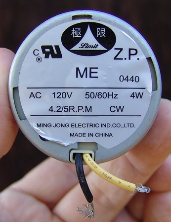
Internal structure of a small laminator motor with a broken gear
(120V, 4W. , 4.2/5 rpm)
Photos by RP. ronaldpatterson@windstream.net
My laminator stopped working, so I removed the motor, ground down the tabs, and opened it up. I discovered several parts of a broken gear.
I chose not to get another gear (or motor), so I got a new laminator. I posted these photos because it's hard to find them elsewhere. (10/22/15)
Fig. 1 Above: Motor front with label. Right: Motor back side with half-moon shaft.
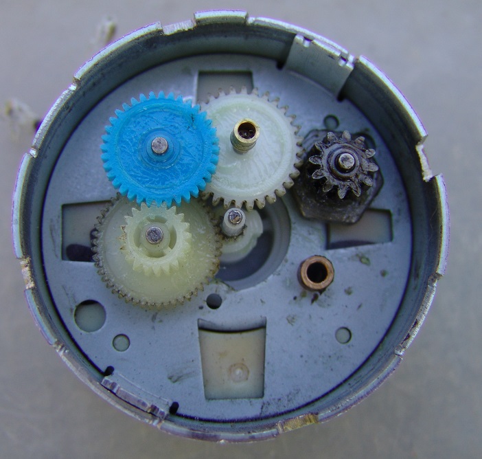
Fig. 2 Above: Internal gears. Main drive axle is center. Also, note black hex. gear at right. Internal output gear sits in copper shaft.
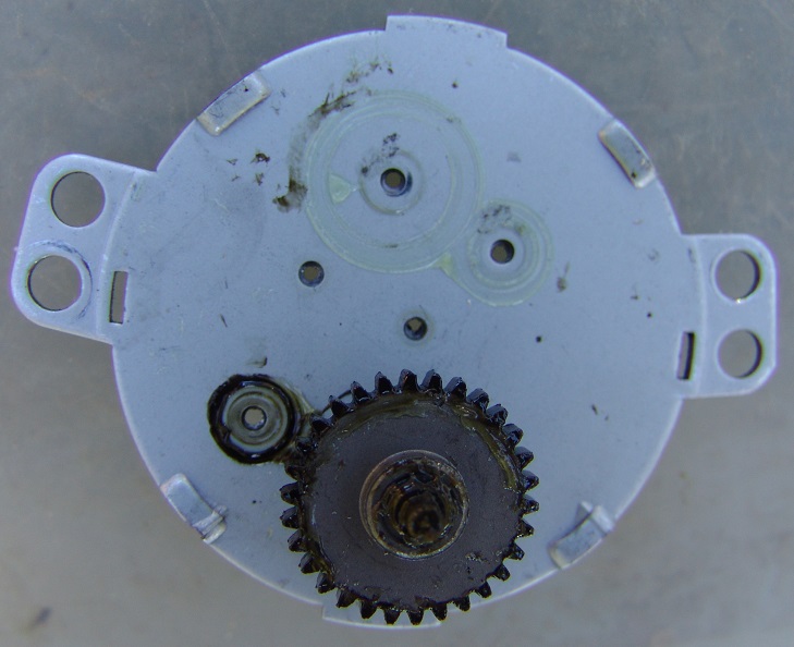
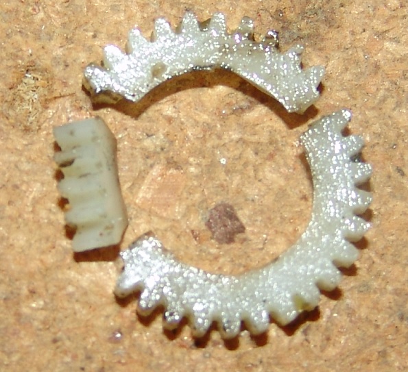
Fig. 3 Above: Internal output gear which attaches to half-moon axle on the other side. The axle (facing you) of this gear goes in the copper shaft.
Right: Shattered gear, which fits around the perimeter of the black hex. gear in fig. 2.
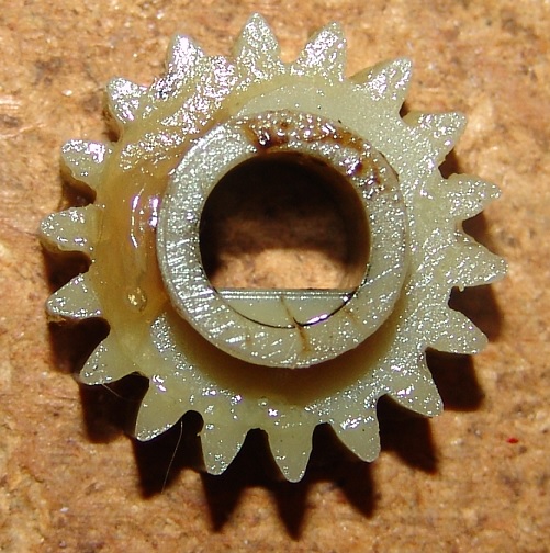
Fig. 4 External drive gear, which sits on the half-moon shaft. This gear interfaces with the laminator rollers.